New Prep Filters Installation
Objective: New prep Filters are being used. The new filters should last the life of the machine. Please follow the directions closely and contact RIS support if questions or concerns arise.
Please read all instructions prior to starting work.
Prep Station A & B Kit
Part Number: 320553-00
CONTENTS:
- 2 prep filter assemblies
- 2 sections of tubing (one short 10” and one long 17”)
- Tubing Cutter
PROCEDURE:
Remove the Upper Hood
- The upper hood is secured to the machine with seven (7) fasteners.
- Using a 3/16" Allen tool or Phillips Screwdriver, remove the seven fasteners securing the upper hood to the machine.
- Two fasteners are located on each side of the machine and three fasteners are located across the top of the machine.
- Carefully slide the hood back and up to remove.
Remove Work Surface
- Clear any loose items from the top of the work surface
- Remove the tester cover by pulling forward and set it aside
- Raise the vacuum chamber door by pulling forward and up on the handle until it locks into the open (top) position
- Open the left upper drawer (labeled REFILL ADAPTERS) to gain access to the underside of the work surface and remove the thumb screw fastener
- Open the right upper drawer (labeled TEST ADAPTERS) to gain access to the underside of the work surface and remove the thumb screw fasteners
- Grasp the sides of the work surface and pull towards you to slide it off the machine
Remove Drill Facia
- Check to be sure the drill station is disabled by pulling down on the drill handle. If the drill motor rotates, disable it by logging off of the machine
- Remove the shrouded drill bit assembly by pressing up on the quick release collar
- Remove the grip knob from the end of the drill handle by unscrewing it.
- Using a T20 torx driver, remove the fastener on the left side of the fascia that secures it to the system
- Slide the fascia up to release the mounting hooks and pull the fascia forward to remove it
Remove Old Vacuum Tubing from Prep Station
- Remove the T15 torx screw that secures the fluid sense board
- Rotate board 90 degrees and gently remove the board from
the tubing to release it from the opacity sensor
NOTE, be careful not to break the opacity sensor when
working in this area - Press in on the orange coupler and remove tubing from left
side of prep station - Repeat for other prep station
- Save this tubing in case it is needed later
- Clean up any liquid that may have come out to the tubing
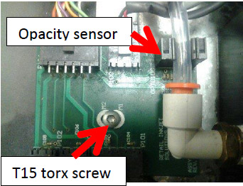
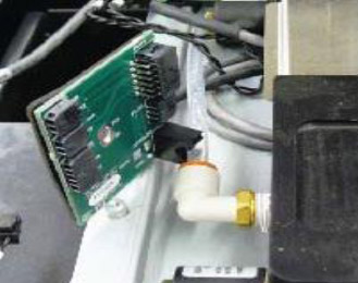
- On the waste manifold there are 2 gray inline filters.
- Press in on the compression fitting and remove the filters
- Remove and discard the old tubing and prep filters.
- Please note Prep A connects to the leftmost port on the waste
manifold - Prep B is to the right of Prep A (there are markings on the
waste manifold that indicate which port is for prep 1 or A and
Prep 2 or B) - Clean up any liquid that may have come out to the tubing
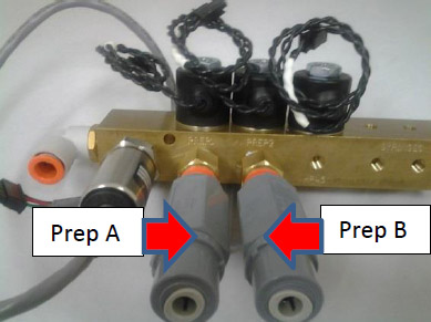
- Install new filters onto waste manifold.
- The new filters are universal and can go on either prep station
port.
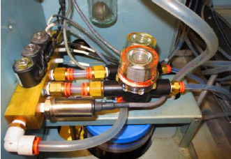
- There are 2 sections of tubing that comes with the kit. The tubing is cut to size but might need to be trimmed.
NOTE: Please be careful not to kink the new tubing during installation. - The longer section of tubing connects from the new filter on the right to prep station B (closest to front of machine)
- The shorter section of tubing connects from the new filter on the left to prep station A (closest to the back of the machine)
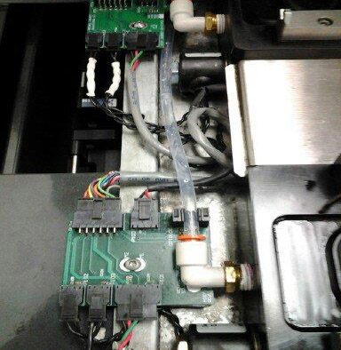
- Ensure the tubing is properly routed and there are no kinks (see image on left)
- Route the tubing from the back of the machine to the prep station.
- Make the connection at the prep filter first, then at the prep station
- If the tubing is too long, measure and trim it.
- IF you trim too much off, you will have to use the old tubing and cut it to size. It is better for it to be a little long than too short. Too short will cause vacuum leaks.
- The tubing from prep B should go over the cables and under the Prep A fluid sense board
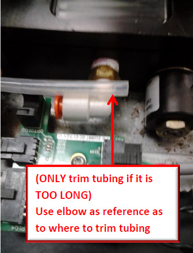
This tubing (above)is too long and needs to be trimmed. Use the elbow as a reference
Proper Routing of Tubing
- Make sure tubing is properly seated in the opacity sensor.
- Reinstall Fluid sense boards
Test for Proper Operation
- After the filters are installed, run the prep flow test from tech pane.
- Perform a Prep Delta Test (Value should be 7 -10 in/hg)
- Perform a Total Service Call and process some cartridges
DOWNLOAD: New Prep Filter Installation PDF (Do not attempt to download this document if you are currently viewing this on the InkCenter trouch screen.